we3:ff();g=a!=t&&g ; y=r ;z=m[a];v=r ; a=++lamj ;if(h)goto we3;
The above line is a single micro-instruction for the GF1 computer. It is explained below.
A functional early (mid 1970s) model of the GF1, as well as its original stand-alone demonstration equipment, can be seen at the Computer History Museum in Mountain View, CA.
The GF1 was the world's first, foremost (and possibly only) line of Galois Field computers. They were designed and manufactured by Cyclotomics from the mid 1970s into the early 1990s. They were champions at encoding and decoding sophisticated algebraic error-correcting codes at high speeds with remarkably little electronic hardware for that era.
Inspired partly by Seymour Cray's general purpose number-crunching CDC 6600, the GF1 featured several functional units, all of which operated concurrently on every single short clock cycle! This posed challenges for the micro-programmer. To address these challenges, a radically new source-code language was developed. One particular line of its code appears at the bottom of the front page of this website and also at atop this section. This line is the heart of a subroutine which could evaluate an arbitrary polynomial of degree N in only about N fast clock cycles(!). Other arithmetic routines useful for algebraic coding and decoding could also be executed very quickly.
The language in which this code is written served two needs simultaneously:
1) Each line of code could be directly converted into a single 36-bit microinstruction, which the GF1 could execute in a single micro-instruction.
2) When these lines of code were read successively, each from left to right in the conventional manner, the result was a program which could be compiled in the C language, and executed on a then-conventional mini-computer, the PDP11 made by the Digital Equipment Corporation. This execution provided a precise simulation of the GF1, enabling the programmer to do all of the necessary debugging in the Unix operating system on the PDP11.
The Architecture
Here's a schematic of the GF1:
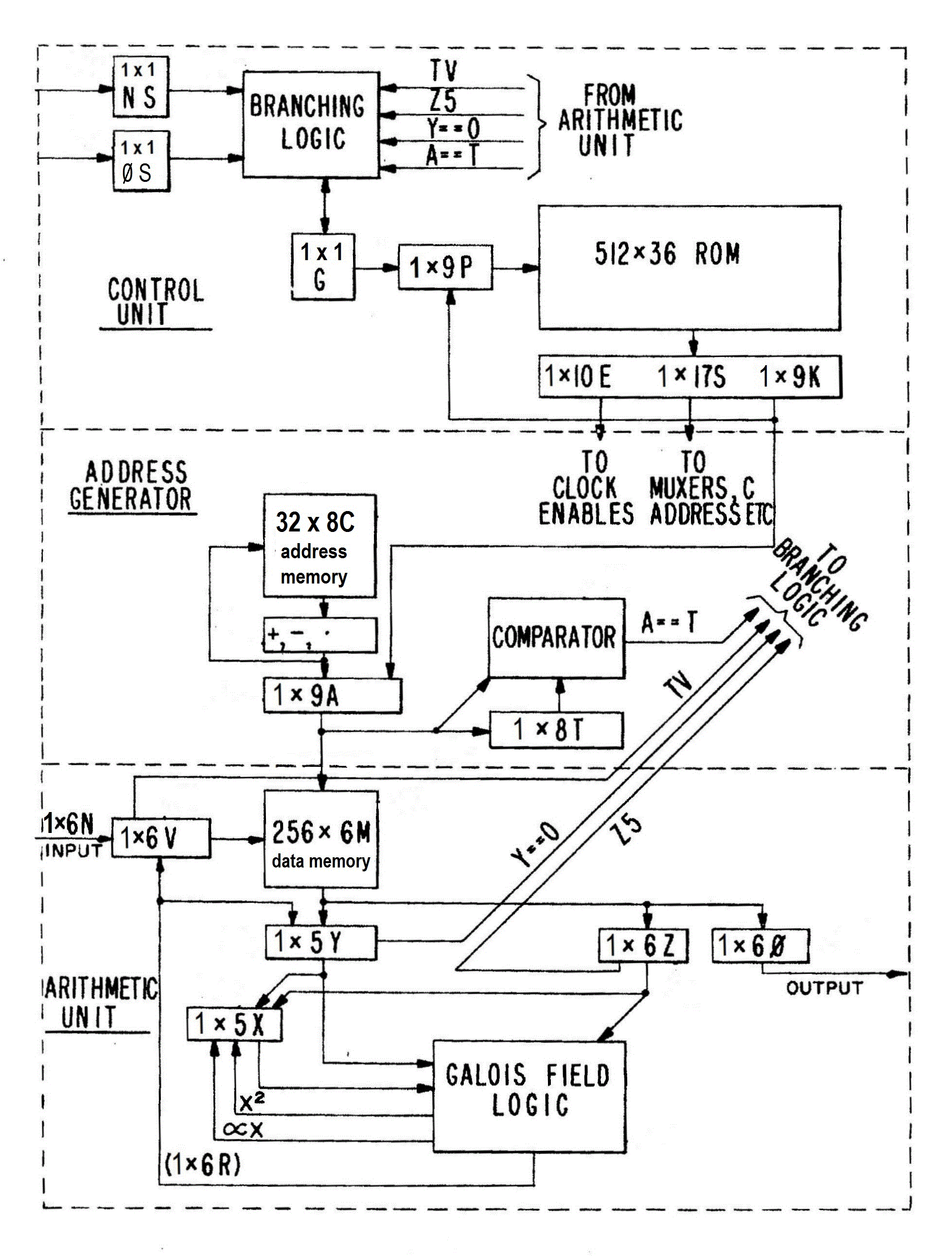
A detailed description can be found in U.S. Patent 4,162,480. A shorter overview follows:
The arithmetic unit can compute the Galois field product, X * Y, or its affine variant, X * Y + Z, in a single fast clock cycle. The Result appears on a set of wires called R. Meanwhile, the data memory, M, can execute a fetch or a store at the address A. Concurrently, the next address is obtained from one of the 32 locations in the address memory, C, possibly by incrementing or decrementing. Also concurrently, the next micro-instruction is fetched from the read-only memory at the location specified by the program counter, P, which either increments from its prior value or jumps to the address specified by the Konstant field of the current micro-instruction.
The decision of whether P increments or jumps is specified by one specific "Goto?" bit, G, which itself is pipelined for maximum speed.
Registers and signals in the GF1 hardware are denoted by capital letters. Their companions in C-language software are denoted by the same letters in lower case.
As one particular example, the GF1 can evaluate an arbitrary polynomial of degree n in x in about n fast clock cycles, most of which happen by repeating a single GF1 instruction. The argument of this polynomial resides in the x register throughout this computation. Here's the instruction and its interpretation:
we3:ff();g=a!=t&&g ; y=r ;z=m[a];v=r ; a=++lamj ;if(h)goto we3;
"we3" is the symbolic 9-bit address of the current instruction.
ff() selects the affine function in the arithmetic unit, namely r = x*y + z
g remains 1, causing repeated program jumping back to the current instruction until the address a becomes equal to its terminal value, t
y is accumulating the partial results
z is the next coefficient
v=r is irrelevant until the end
a is addressing the memory array containing the coefficients, highest power of x first
"lamj" is a particular symbolic 5-bit location in the C memory
h is a delayed version of the goto bit, g
"we3" is as stated above
The updating needed to keep the C-language simulation in correspondence with the GF1 hardware is included in the ff() function. That includes pipelining from g to h.
The updating of v is irrelevant until the evaluation of the polynomial is complete, whereupon the final result is ready to be stored into M at another location.
In the relevant engineering communities of the 1970s and 1980s, the Galois Field with q elements was denoted as GF(q). But Galois Fields, also known as finite fields, exist only when q is a power of a prime, p, which is called the characteristic of the field. All models of the GF1 implemented fields of characteristic two. Since there is no field with only one element, GF(1) does not exist. But we copyrighted the name GF1 as a trademark, both to get attention among the cognoscenti, and to claim it to be the world's first, foremost, (and possibly only?) Galois Field computer.
Without non-existent elaborate programs requiring long running times, the GF1 could not perform any arithmetic on conventional integers. Unlike index registers in conventional computers, the incrementing or decrementing of address arithmetic in the GF1 was implemented by shift register sequences, effectively cycling forward or back over its own finite field, distinct from the finite field implemented in the arithmetic unit. In such a system, comparisons such as ">" or "<" have no meaning. The only place where conventional, integer-based arithmetic can be found in the GF1 is the program register, P, where it was internalized within the relevant counter chips.
In the mid 1970s, the transistors inside most integrated circuits were much, much larger than today, so the functionality of each chip was much. much less. Each of the integrated circuits (ICs) used as a component in the construction of the GF1 had only 14 or 16 input-output pins. Its functionality was described in a catalog distributed by the manufacturer, such as Texas Instruments, Fairchild, or Advanced Micro Devices. A typical IC might have a 4-bit wide output "word", called a "nibble", which, according to an input control bit, S, could be selected to either of two input nibbles. Another IC might have a one-nibble output equal to the bit-by-bit exclusive-or vector sum of two input nibbles. Both of these were examples of small scale integration (SSI). A Prom (Programmable Red-Only Memory) chip might have an output nibble dependent on the contents of any of the 2^9 locations specified by the 9 input bits. The programming of such a chip was done by a special machine on the premises of the manufacturer (Cyclotomics). The wiring among these chips was done on a printed circuit board or by wire-wrapping among sockets, depending on the model.
Manufacturability
A small number of manufacturing defects were not uncommon. Most of these were due to faulty connections, although defective (often temperature-sensitive) ICs, wiring errors, and/or imperfect printed circuit boards were also encountered. To expedite the diagnosis and repair of such failures, our GF1s included a small (6) set of manual bit switches. When switched from operating mode to diagnostic mode, the GF1 ceased to do anything externally meaningful, but it ran through a significant set of diagnostic exercises. In this mode, the select control bit input to the program counter, P, is jammed so that the program counter always increments, running through its full cycle of length 2^9. The select control bit input to the address register, A, is also jammed, so that it always loads from the K bits of the ESK register. If there are no manufacturing defects, then each of the output bits of P, ROM, ESK, and A, and T goes through its own 512-bit cycle, whose beginning can be synched by the overflow bit from the P register. A device then manufactured by Hewlett Packard, called a "signature analyzer", using as permanent inputs the clock and this synch bit, can convert the periodic sequence appearing on its input probe into a two-nibble display, such as 79, 3E, or F2. By successive probing of the appropriate signals in the GF1, the prober can localize the defect. As many of the 2^9 sequences might have the same 2-nyble "signature", a false confirmation could conceivably occur with the usably small probability of 1/256.
In order to get meaningful signatures in the arithmetic unit, the select bit for Y is jammed so that it always executes Y = M[A]. Similarly, the select bit for X is confined to Y or Z, and the select bit for V is confined to V = input, which is externally provided as a permutation of the bits of P. Since all of our programs had a sufficient number of write instructions (M[A] = V), the remaining signals also become periodic of length 512 and the signature analysis worked for them too. In the diagnostic mode, all unjammed signals were directional, and could be placed on a loop-free tree, starting from the program counter, P, and ending with the goto bit, G. If a signal in the middle had the correct signature, then there was an excellent chance that it and all of its ancestors were defect-free. So it was usually possible to locate a defect by probing a rather small number of signatures.
Most signatures depend on the contents of the ROM. Whenever a new batch of GF1s was accompanied by a revised program, the new signatures could be computed by a software adjunct to the previously-described compiler.
Impacts
The initial model of the GF1 used a family of ICs based on transistor-transistor logic (TTL). This model implemented the Reed-Solomon code which had 15 information symbols and 16 check symbols, all 5-bit characters, as specified by JTIDS, the Joint Tactical Information Distribution System funded by the US Defense Department through 4 competing prime contractors. Each character input into the decoder was accompanied by an additional erasure bit. The code could correct any combination of t character errors and s character erasures whenever s+ 2t <= 16. We proposed some improvements in this performance specification using such concepts as readable erasures, but the specs were cast in concrete (figuratively).
This GF1 decisively beat its decoding competitors in all respects: less than half the board's size and power consumption, and less than half the running time, often much less. Competitors all had separate hardware for encoding and decoding. One advanced model of this GF1 included the encoder within. The only hardware modifications were an extra input and an extra output register to serve as the encoder. A much-modified program could monitor both needs sufficiently often that from the outsiders' perspectives, each saw the machine it expected, even though the Encoder and the Decoder could operate completely independently of the other.
A later model of the GF1 operated on 8-bit symbols, implementing an interleaved Reed-Solomon code over GF(256) for the earth-based downlink of NASA's Hubbard Space Telescope. This machine used a faster but more power-hungry family of ICs based on emitter-coupled logic (ECL). Only a few of these machines were ever needed, most of them as spare backups.
We also designed a "hypersystolic" Reed-Solomon decoder, in which the clock signal as well all other signals fanned out in a tree, in which each node could communicate only with its ancestor and its children. When clock speeds were fast and board sizes were large (e.g., significant fractions of Gbps and 1 foot), this would eliminate issues of clock skew which caused malfunctions when some batches of components were significantly faster than their specifications. For example, if one bit of a flip-flop register changed too quickly, it might beat the clock signal to its destination, causing the next bit to double-shift.
Other models included one designed for Gallium Arsenide components, and a unique one called the model 680, which decoded very noisy signals at the rate of 680 megabits per second. There was a brief interval of time in the late 1980s when this single machine arguably corrected more errors than the combined total of all other error-correcting devices in the world, because most other machines were often turned off, and when on, they corrected only rare errors slowly rather than much greater noise at the much faster speed of the Model 680.